There is a growing interest, both in industry and academia, in using microfluidic techniques (e.g., cross-flow, flow focussing, and co-flow) to generate droplets in a controlled manner. Such processes are used in many different industries, including biomedical, pharmaceutical, and chemical. A schematic illustration of typical experimental set up used in a laboratory to investigate droplet generation is shown in Figure 1. Applications of droplet generation in microfluidic channels include the production of food, cosmetics, and pharmaceutical products, as well as in biomedical diagnostics (Lab-on-a-Chip).
Why are T-junctions a popular choice of geometry for microfluidic droplet generation?
One of the most frequently used geometries to investigate droplet formation, both experimentally and theoretically, is a microfluidic channel which a sidewall inlet, known as a T-junction (see Figures 2 and 3). They are simple geometries to construct and design, and can lead to high rates of droplet generation. Droplet generation in microfluidics is a highly complex process, depending on coupled velocity and pressure fields, as well as phase interfaces, all of which dynamically vary with time. Certain equations for simple cases (channel geometry, flow rate) do exist in the literature, but for many of the large range of possible applications, finite element modelling is a critical study and design tool.
Xi Engineering has experience in the mathematical modelling of fluid flow systems, including microfluidic channels. Our approach is to use our existing knowledge to develop thorough mathematical models to explain complicated processes.
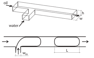
Figure 1: Schematic illustration of a typical experimental set-up and of the process of droplet generation in a microfluidic channel using two immiscible fluids. (Figure adopted from Garstecki et. al., Lab Chip, 2006, 6, 437-446).
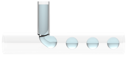
Figure 2: Example of how droplets are formed in a microfluidic device with a T-junction. The break-off of droplets occurs due to a back pressure in the continuous phase as the disperse phase emerges into the main channel. (Figure adopted from elveflow.com, accessed 13/12/2021).
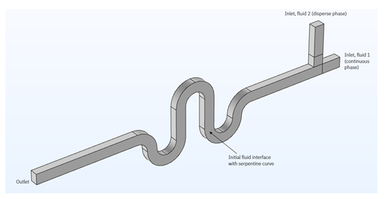
Figure 3: A typical modelling domain of a microfluidic channel which consists of a T-junction and a serpentine curve between the channel inlet and outlet.
How are droplets formed in microfluidic channels with a T-junction?
The process of droplet formation in microfluidic channels with a T-junction is based on using two immiscible liquids, one of which is referred to as the continuous phase (in the “main” channel) and the other is known as the disperse phase. The disperse fluid initially flows perpendicular to the continuous flow. When the two liquids meet at the T-junction of the channels, the disperse phase begins to enter the main channel. In the regime where viscous forces are dominated by surface tension forces, the propagation of the disperse phase into the main channel leads to an increased resistance to the flow of the continuous phase, thereby increasing the pressure in the main channel behind the emerging droplet. When the pressure behind the emerging disperse phase becomes high enough, a neck is created. The emerging disperse phase continues to “block” the main channel flow, increasing the pressure, which in turn causes this neck to get smaller, until it becomes unstable and snaps, separating off and forming a droplet. The droplet then travels forward, entrained in the continuous phase flow. Ideally, the process of droplet formation occurs at a high rate, with droplet break-off occurring at regular intervals at the same point in the channel, resulting in repeatable, well-controlled droplet size and spacing.
Modelling of droplet generation using COMSOL Multiphysics
A study performed by Xi Engineering is shown below using COMSOL Multiphysics, specifically the Laminar Flow and Level Set modules. These modules are highly flexible to allow the user the ability to account for the correct physics needed to model different situations. By obtaining suitable values for the fluid properties and geometric parameters from the literature, we solve the fully coupled non-linear system of equations numerically.
Animations showing the process of droplet generation
Experimental and theoretical investigations of the most typical lab-on-a-chip channel configurations have shown that when the forces due to viscosity are dominated by those due to surface tension (i.e., small Capillary number), the size of the droplets produced is determined by the continuous and disperse phase flow rates. If we take the two examples shown in Animation 1, we can see that the two immiscible fluids form an interface at the junction of the inlet and main channel.
The stream of the disperse phase (blue) emerges into the main channel, and a droplet begins to grow; the pressure gradient and the flow in the main channel distorts the droplet in the downstream direction. The significant difference between the two results in Animation 1 is that we can see that the positions in the channel at which the droplets form and the droplet distribution across the channel are different. In Animation 1, top, we can see a continuous parallel-flow regime trailing a few initially-formed droplets. By increasing the continuous phase flow rate and keeping the disperse phase flow rate constant, a more regular and repeatable droplet formation with breakoff near the junction occurs (Animation 1, bottom). This change in the fluid distribution across the channel is due to changing the flow rate ratio.
Alternatively, one could reduce the disperse phase flow rate to promote more rapid droplet generation. The disperse phase flow rate must, however, be high enough that it has sufficient driving pressure to be able to emerge into the main channel in the first place – otherwise no droplets form at all! The process of repeated droplet generation is highlighted as well in Animation 2, where we plot an isosurface of the volume fraction of fluid (i.e. the boundary between the phases).

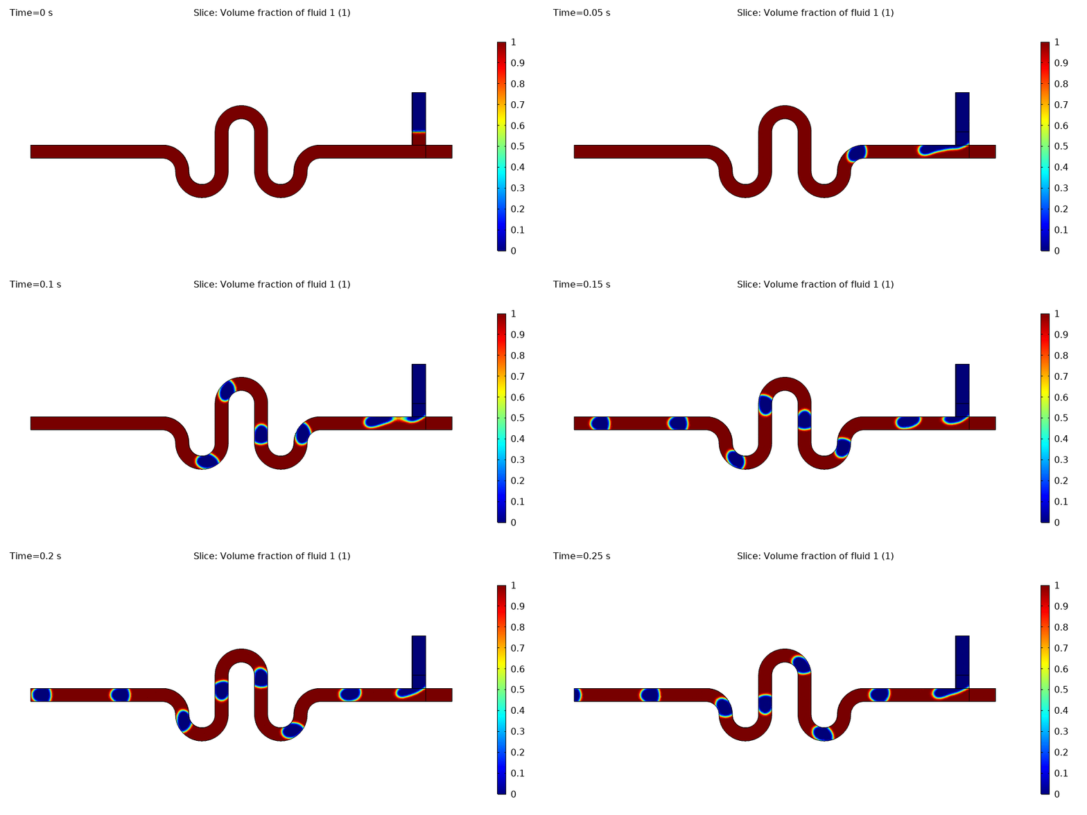
Animation 1: Animations of the volume fraction of two isotropic liquids in a microfluidic channel containing a T-junction and a serpentine curve.
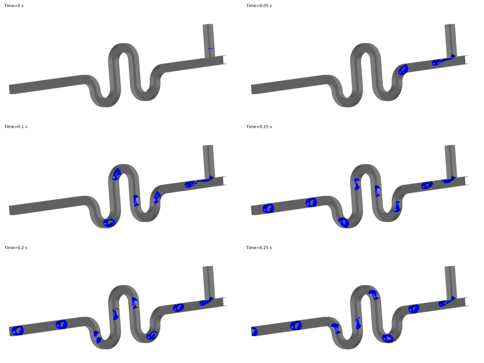
Animation 2: Volume fraction isosurfaces in 3D, showing highly regular droplet break-off and spacing.
Mixing in Droplet-Based Microfluidics
One major reason for using droplet-based microfluidics is that they substantially enhance mixing processes, for example when chemical reactions are being performed. Separate reagents may be suspended or dissolved in each of the phases, with reactions occurring at the phase interfaces. The travel of the droplets, along with surface tension effects forms recirculating vortices (relative to droplet surface), continually replenishing reagent and recirculating product.
Dean vortices are generated when fluid flows around curves, and further enhances mixing processes. These lateral vortices occur over the channel cross-section because of differential centrifugal forces acting on the fluid as it rounds a curve. These vortices may occur either with or without droplets present.
Xi Engineering’s expertise and capabilities
Xi Engineering are experts not just in microfluidics, but also have capabilities in the mathematical modelling of anisotropic liquids (e.g., liquid crystals) and other non-Newtonian fluids. On a larger size-scale, Xi also has extensive experience in computational fluid dynamics (CFD) for wind microclimate studies, which are used in commercial/residential construction planning and consent.
If you have a project that focusses on fluid mechanics and want to explore new ways to interpret and understand their behaviour in various geometries with different boundary conditions, we may be able to aid in developing mathematical models using numerical software packages such as COMSOL Multiphysics.
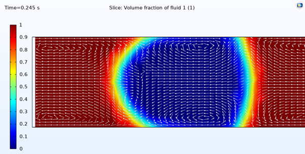
Figure 4 : The volume fraction of fluid as a droplet propagates from right to left, illustrating how surface tension mixing occurs. The arrows indicate the direction of the velocity field, relative to the droplet surface, where chemical reactions will occur.
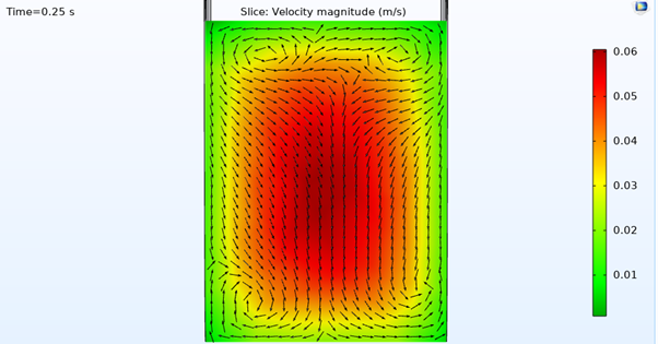
Figure 5 : The cross-sectional slice (colour field) shows axial velocity along the main channel flow direction, and the vector arrows are lateral velocity components, showing the transverse Dean mixing process.


