Most people have, at some stage, been taught that matter exists in one of three states: solids, liquids, and gases. This rather simplified system of classification of matter has been shown to be inadequate for many materials (e.g., plasmas and superfluids). Liquid crystals are an important example of a state of matter where the basic solid/liquid/gas classification is not suitable.
What are liquid crystals and why are they important?
As the name suggests, liquid crystals are materials which share some structural properties that are found in solid crystals (e.g., diamond), while at the same time displaying flow behaviour observed in classic liquids (e.g., water). They can therefore be thought of as an intermediate state of matter, existing between the solid and liquid phases (see Figure 1). In liquid crystal materials, the molecules lose the positional ordering found in solids, but not their orientational ordering (i.e., how the molecules are aligned in a sample). The orientational ordering and fluid flow in liquid crystal materials are coupled to each other, where molecular rotation can cause flow and vice versa. In classic liquids, the molecules have no positional or orientational ordering.
Liquid crystals were first discovered in 1888 by the chemist Friedrich Reinitzer, who observed that heating a sample of cholesteryl benzoate (a solid at room temperature) led to two melting points. The first of the melting points occurred at 145.5°C and led to the formation of a cloudy liquid. Upon further heating, a second melting point occurred at 178.5°C, at which the cholesteryl benzoate turned into a transparent liquid. The cloudy liquid reported by Reinitzer is now known to be a liquid crystal phase. Reinitzer sent a letter to the German physicist Otto Lehmann, along with two samples of cholesteryl benzoate, in which he requested an investigation to confirm his experimental observations. Examination of these samples led Lehmann to use the expression “flowing crystals” to describe these samples, before eventually settling on the term “liquid crystals” in 1900.
Since the invention of the first liquid crystal display in 1964 at RCA Laboratories in Princeton, New Jersey, liquid crystals have been the focus of an active and highly interdisciplinary research community, including chemists, engineers, mathematicians, and physicists. Each of these areas continue to make substantial contributions to the development of liquid crystal technologies in a wide range of applications which we make use of in our everyday lives (see Figure 2). Under current projections, the worldwide liquid crystal industry is expected to reach a market value of $1.8 billion by 2026, and currently is valued at $1.2 billion. Each year, an estimated 2 billion liquid crystal display units are sold each year across the world. This is an industry which continues to grow, with a high increase in demand for liquid crystals for the development of future generation technologies (e.g., 5G and 3D printing, and head up displays (HUDs) for car dashboards).
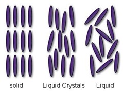
Figure 1: Schematic illustration of a typical arrangement of molecules in solids, liquid crystals, and liquids. (Figure adopted from http://phelafel.technion.ac.il/~hilag/tutorial/whatIsLC1.html).

Figure 2: Examples of everyday devices in which the screens have been designed using liquid crystal technology.
Theoretical modelling of liquid crystals
A crucial factor in the development of liquid crystal display technology is the theoretical understanding of how these displays operate. Since the 1930s, there have been numerous theories of liquid crystals, each of which have their own complexities. The first accepted dynamic theory of liquid crystals, namely the Ericksen-Leslie theory, first developed by Jerry Ericksen in 1961 and completed by Frank Leslie in 1968 (see Figure 3), continues to be of significant interest to the liquid crystal community. For example, engineers have used the Ericksen-Leslie equations to optimise flat-screen displays found in laptops, TVs, and mobile phones, making them thinner, faster, and capable to producing images with a higher resolution. Over the decades, mathematicians have used these equations to advise engineers and material scientists on how to construct liquid crystal displays to achieve the best possible device performance. The Ericksen-Leslie theory has been so influential to the development of liquid crystal technology that there will be at least one screen that we use daily (e.g., computers/laptops, mobile phones, and watches) that will have been developed by material scientists and engineers with the aid of the Ericksen-Leslie equations.

Figure 3: Pioneers of the Ericksen-Leslie dynamic theory of liquid crystals. Frank Leslie (left) and Jerald Ericksen (right). (Figure adopted from R.J. Atkin and T.J. Sluckin, Biographical Memoirs of Fellows of the Royal Society, pp 315 – 333, 2003).
A basic description of liquid crystal materials
Most of the materials that are known to exhibit liquid crystal phases are organic substances, with two classic examples shown in Figure 4. Liquid crystal molecules are anisotropic and can be thought of as rod-like or disc-like in shape. It is because of the anisotropic nature of the molecules in liquid crystals that orientational ordering as well as fluid flow must be considered when describing liquid crystal materials.
There are several possible liquid crystal phases, each with their own distinct structural characteristics. In the simplest description, introduced by Georges Friedel in 1922, the classification scheme used for liquid crystal phases consists of three categories: nematic, cholesteric and smectic. In the nematic (or achiral nematic) phase the long axes of the constituent molecules tend to align parallel to each along a single preferred direction referred to as the anisotropic axis. The cholesteric (or chiral nematic) liquid crystal phase is like the nematic phase, except that the molecular orientation shows a preferred helical configuration. This helical structure arises from the chiral properties of the constituent molecules. Smectic liquid crystals are layered structures and are, therefore, more ordered than the nematic phase and generally occur at lower temperatures than that of nematics. The molecular arrangement in each of these three liquid crystalline phases is shown in Figure 5. The nematic phase is most used in developing a liquid crystal display and will be the phase we concentrate on in this blogpost.

Figure 4: Two examples of organic structures in liquid crystal materials. (Figure adopted from here)
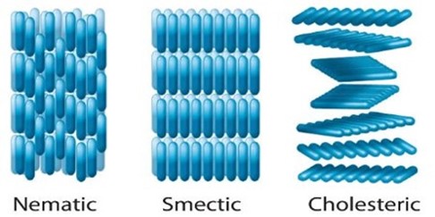
Figure 5: Schematic illustration of the molecular arrangements in the nematic, smectic and cholesteric phases. (Figure adopted from https://qsstudy.com/chemistry/liquid-crystals).
How nematic liquid crystal displays work
Liquid crystal materials are used in a huge range of display devices – from mobile phones, TVs to car dashboard displays. These materials can interact with applied electric fields and light, which allows them to switch between two optically different states – and can therefore be used to construct displays. An animation which summarises the process of how a liquid crystal display operates is shown in Animation 1, where such devices consist of two substrates which are normally made from glass, each with a transparent conductive coating that acts as an electrode. A layer of nematic liquid crystal is then sandwiched in between the two substrates. Liquid crystal display technology works by controlling the amount of light that is allowed to pass through. First, a source of light is moved through a polarizer and first substrate, into the liquid crystal layer. The polarizer restricts the amount of light which passes through to a single plane, leading to plane polarised light. By placing electrodes round the liquid crystal, an electric field (or voltage) can be used to change the orientation of the molecules. Provided the applied voltage is high enough, the rotation of the molecules then allows varying levels of light to pass through to the second substrate. A colour filter is included before a second polarizer filter to create the colours and images seen on an LCD. These images consist of an array of pixels, where each of the individual pixels can be switched on or off very rapidly using a transistor to make the moving colour picture.
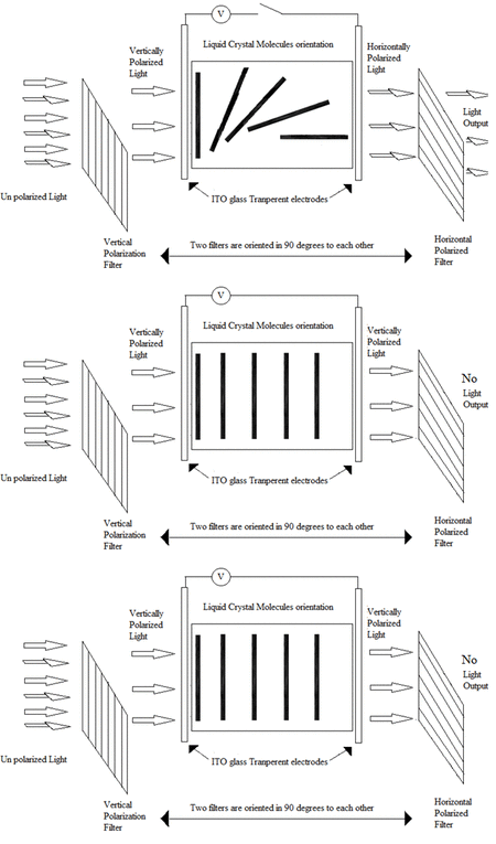
Animation 1: Operation of a typical liquid crystal device. (Animation adopted from https://gifer.com/en/UiWi).
Topics of significant interest in the development of nematic liquid crystal devices
As mentioned before, liquid crystals are used in the designing of many displays – from mobile phones, computers and TVs to car dashboard displays. The ability of liquid crystals to interact with light, and applied electric fields, means that they can switch between optically different states – and can therefore be used to construct a display. Standard nematic liquid crystal displays consist of a two-dimensional array of pixels, each of which can be individually switched, thus forming a two-dimensional pixelated image.
One industry which has significant challenges with using standard nematic displays is the automotive industry, with safety being the main driving factor behind developing new technologies which allow drivers of motor vehicles, such as cars, to maintain sight of the road while reading the display. As a result, the automotive industry, amongst others, have now started designing head-up displays (HUDs). More generally, a HUD is a transparent display that presents information which does not require viewers to alter their field of vision (see Figure 6). Standard approaches use an image projected onto the windscreen, producing a 2D image. However, with dynamic holographic techniques, nematic liquid crystal layers can be used to create an augmented reality HUD.
Unlike standard liquid crystal displays, holographic devices require a much denser array of pixels, which require smaller pixel elements. This reduction in pixel sizes leads to the molecular orientation of the liquid crystal changing rapidly over extremely small length scales, creating regions of high distortion close to pixel edges called fringing fields. These regions can hinder the optical performance of a liquid crystal display because of localised melting in the display. As a result, there is significant interest, both in industry and academia, in adapting the shape of the pixels to minimise the unwanted effects of fringing fields in HUDs. Given that there are numerous material and geometric parameters in a liquid crystal device, a full optimisation of these materials challenging, time consuming and expensive. The development of mathematical models of these materials is of crucial importance in enhancing our understanding and in the future development of HUDs and holographic technologies. As well as the increasing safety on the roads, future applications of holographic technologies include:
- Telecommunications (e.g., for reconfigurable optical interconnects such as wavelength selective switches for high-speed internet).
- Medicine (e.g., restoring sight using gene therapy and 3D projection glasses).
- Data and information storage in 3D.
- Protection against ID fraud.
Xi Engineering’s expertise and capabilities
Xi Engineering has experience in the mathematical modelling of fluid flow systems, including (non)-Newtonian fluids and porous media. Our approach is to use our existing knowledge to develop thorough mathematical models to explain complicated fluid flow processes. Xi Engineering are experts not just in the mathematical modelling of Newtonian fluid systems using computational fluid dynamics (CFD), but also have capabilities in the mathematical modelling of anisotropic liquids (e.g., liquid crystals) and other non-Newtonian fluids. If you have a project that focusses on the fluid mechanics of liquid crystalline systems and want to explore new ways to interpret and understand their behaviour in various geometries with different boundary conditions, we may be able to aid in developing mathematical models using numerical software packages such as COMSOL Multiphysics.
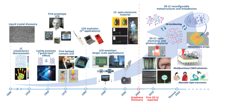
Figure 7: Timeline of the history of liquid crystal applications, from their discovery in 1888 to the present day. (Figure adopted from B.T. Hogan et al., J. Maters. Chem. C, 2017, 5, 11185).


